
Quozl's Linux Speedometer, Odometer, and Trip Computer |
| quozl@us.netrek.org
| up |
|
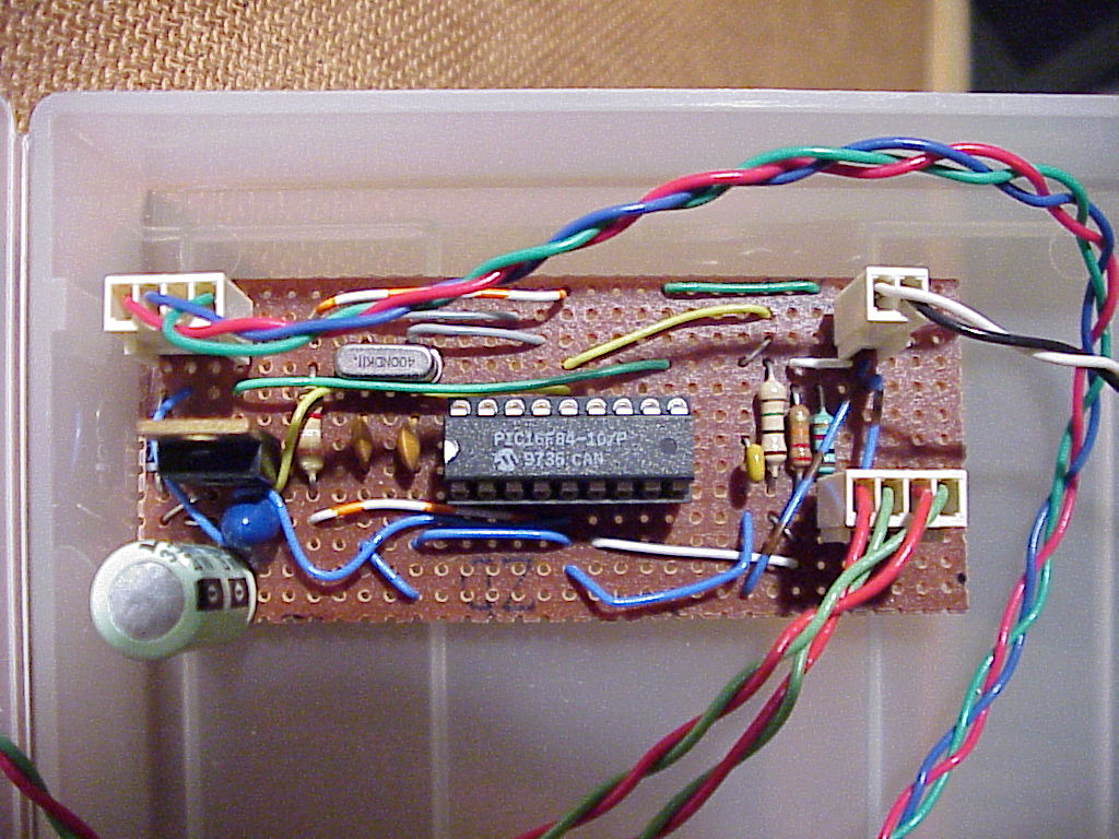
assembly |
sampler |
laptop |
The data stream from the microcontroller to the laptop consists of an initialisation marker on power up "a\r\n", followed by regular lines of text containing ten digit ASCII values for the counters, separated by a space. The time in milliseconds is output first, followed by the revolution counter. For example:
a
0000000500 0000000000
0000000997 0000000007
0000001481 0000000014
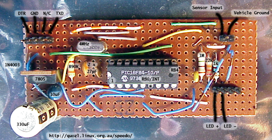
Also available is an annotated circuit board image. Where it says 890k, read it as 3.9k.
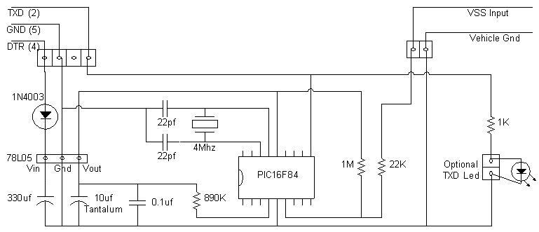
Schematic courtesy of John, though with the same 890k vs 3.9k error. My fault.
The two 22pF capacitors and crystal form the precision timing source for the microcontroller. The 3.9k resistor is a pull-up for the MCLR reset input of the PIC.
Input filtering of the oscillating 12V VSS input is via a series 22k resistor and a 1M pull-up. The PIC input port clamping diodes are used to restrain the voltage at RB0/INT, which is configured as an input.
The RB4 pin is configured for output and generates an pre-inverted TXD serial data signal to the laptop. An optional LED on the prototype was used to indicate transmissions.
No other pins on the microcontroller are used. Clearly, there is ample room for an LCD display and keypad.
The interrupt service routine (ISR) is therefore called at 4808Hz. The ISR performs these actions;
At the start of the ISR, the TMR0 register is preloaded to a value calculated based on the number of instructions executed by the processor since the ISR began. The calculation is hand-crafted and depends on the instruction stream. This allows TMR0 to be operated as a 208 microsecond repeating interrupt source, rather than using the counter in a free-run mode.
Because it is known that each interrupt occurs 208 microseconds from the last one, a 16-bit counter is used to accumulate time since the last whole millisecond. The ISR adds 208 microseconds to this counter. When the counter reaches a number above 1000, one millisecond has passed. The counter is reduced by 1000 microseconds, leaving the remainder. Thus a portion of the ISR is executed for every one millisecond, but the actual instant of execution drifts by up to 208 microseconds.
The ISR fragment that is executed every millisecond updates a 32-bit millisecond counter, and sets a flag so that the non-interrupt level code can be woken.
Next, the remainder of the ISR is executed, still at 208 microsecond intervals. It checks to see if serial data is being transmitted, and if it is, the next bit is shifted out to the RB4 output pin. Finally, the input pin RB0/INT is checked to see if it has changed state. If it has turned on since it was off (208 microseconds ago), then a 32-bit counter of cycles is incremented, the main code is woken, and a 4ms debounce counter is set. Changes to the pin state are ignored until the debounce counter reaches zero after around 19 more interrupts.
The main code performs these actions:
The program also allows entry of waypoints, or marks, whereby a name can be associated with a particular odometer value. The first keystroke of the name is used to read the odometer, and the return key writes the entry to the log. As an additional feature, if the mark name is a number, it is assumed to be distance to a destination, and the program calculates and displays average speed since the mark, remaining distance to the destination, and expected arrival time.
Initial calibration was by dangling a plumb bob or pointer from the left passenger door, such that it was a few millimetres off the concrete. The vehicle was allowed to move (by gravity) until the VSS output changed state (e.g. off to on). A mark was placed on the concrete, and the vehicle rolled again until the VSS output changed state back, and then full cycle (e.g. on to off, delay, then off to on again). Another mark was placed. The distance between the two marks was then measured, using a millimetre ruler.
Subsequent calibration was done against both the vehicle speedometer and a GPS. The value of mm was changed in real-time in an older version of the code, by creating a file calibrate.dat with a new value. Once we'd finished calibration, we disabled that section of the code.
Code to be removed:
L96:            ignore                  ; cycle input debounce timeout (1ms)

L154:   decfsz  ignore,f                ; decrement and test debouncer timer
        goto    isr_clock_end

        incf    ignore,f                ; restore to unity

L195:   decfsz  ignore,w                ; test the ignore timer
        goto    isr_cycle_end           ; if running, continue to ignore
        movlw   d'4'                    ; set 4ms debounce ignore
        movwf   ignore

L208:   decfsz  ignore,w                ; test the ignore timer
        goto    isr_cycle_end           ; if running, continue to ignore
        movlw   d'4'                    ; set 4ms debounce ignore
        movwf   ignore
| Date | Change |
|---|---|
| 2005-06-25 | Initial calibration described. |
| 2003-08-18 | Change of name and web site link for a contributor. |
| 2003-05-23 | Fixed Makefile for more recent versions of gpasm, thanks to Craig Franklin. |
| 2001-10-19 | Wrote up adjustment for higher sampling rates, for Gerald, whose return mail address bounced. |
| 2001-04-11 | Add schematic provided by John, and wrote up the theory of operation |
| 2001-04-08 | Add close-up annotated photograph of prototype |
| 1999-11-01 | Add photographs of prototype |
| 1999-07-07 | Initial page |