Quozl's Temperature Sensor Project |
| quozl@us.netrek.org
| up |
|
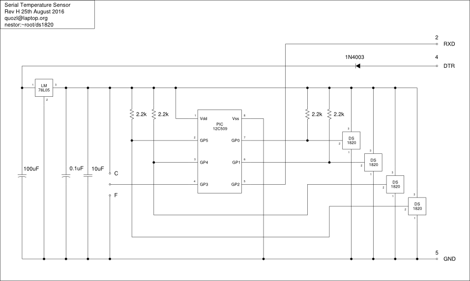
One of my units began to report Fahrenheit occasionally. Turned out GP3 was floating. Added a strap to the C pin on the PCB and all is good now.
Amazingly, this also showed the C and F labels on the schematic were swapped, along with the description of GP3 in the text below from 2001.
Here's a revised schematic.
There have been a couple of reports of missing digits in the data stream from the microcontroller to the host.
I have a theory. The PIC 12C509 is meant to be programmed in a specific way by the seller. The code space contains a preprogrammed calibration constant for the internal R/C oscillator. The instructions that I provided to the original seller Kitsrus specifically excluded the memory address for the calibration constant, so that the constant set in chip manufacturing process would be left intact.
However, if someone has later attempted to duplicate the code from one PIC 12C509 to another, this might result in an incorrect calibration constant for the oscillator. It is impractical to correct, since the PIC 12C509 with plastic top is a one-time-programmed part.
As a result, the asynchronous serial data would not exactly match the baud rate expected by the serial port. Characters would be dropped.
If you were to analyse the electrical signal on the serial port, and compare the timing against the baud rate, you may find that is the cause of the problem.
Of course, the timing source in your serial port, or USB to serial converter might also be a source of the symptom!
gpasm has changed since this project began, and rather than obtain an old version, you can use a current version of gpasm. You need certain flags:
gpasm --ignore-case \
      --processor 12C509 \
      --warning 1 \
      ds1820.asm
That said, I've not tested that it works on chip!
George asked I already own a temperature kit (it works perfect in my serial port) and I would like to know if it is compatible with USB to Serial adapters?
Perhaps. The original design was not compatible with all serial ports, and so it is entirely possible that it might not be compatible with some USB to serial adapters.
If you're able to see into the adaptor and detect a small integrated circuit of about 16 pins that is labelled MAX232 with about four capacitors around it, then it is likely to work. The MAX232 or equivalent raise the operating voltage to meet the standard.
If you are able to test the adapter first by measuring the voltage of a signal line like DTR with respect to the GND pin, (this will be non-zero just by plugging it in to a USB port, no application should need to be run), ... if you get around 5V, then it probably won't power the temperature kit well ... but if you get around 12V it should work fine.
You can also modify the temperature sensor kit for an external 12V DC supply, by disconnecting the DTR trace from the connector to the diode, and connecting 12V DC there. Instead of powering the microcontroller and sensors from the DTR signal, it will be powered from your external source.
You can also modify the temperature sensor kit to use the USB supply voltage, by connecting the 5V line from the USB cable (the computer side of the USB to serial adaptor) to the 5V *output* of the voltage regulator.
As the copyright owner of ds1820.asm below, which is licensed under the GNU General Public License, I would like to hear from anyone who has purchased a microcontroller which contains a work derived from this, and who has not been able to obtain the source code of the version on the chip.
The information I would like you to include:
James Cameron.
Want to contribute to tsl, or run it on Debian?
Quozl continues to get mail about this project. This is quite encouraging! But he lost the mailing list and doesn't plan to recover it.If you are wanting help, or are willing to help others, please visit the project community page.
| Country | Organisation | Item Number | GPL Compliance | Date Checked |
|---|---|---|---|---|
| Australia | Ozitronics | K145 | Complete | 13th June 2003 |
| United States of America | Carl's Electronics Inc | CK110 | Partial | 13th June 2003 |
| Kingston, Ontario, Canada | QKits | QK145 | Complete | 13th June 2003 |
| Hong Kong | Kitsrus | K145 | Complete | 13th June 2003 |
| Denmark | eekit.dk | 0104-K145 | Partial | 29th November 2004 |
(If you also sell this kit, and you would like to be added to the list, please write to me, including your country, organisation name, links to your web site and to the kit page. There is no reciprocal link condition. You may be asked to provide a link to this page, but that is for compliance with the software license.)
The data from the DS1820 arrives in a format peculiar to the sensor. The program calculates the temperature from the data and translates it into human readable ASCII digits. No special program is required on the computer.
     R V1.0 1999-12-21 22:05:03 C
     1 0022.50
     2 0022.47
     3 0022.52
     4 0022.53
|
The sensor data is reported in the international standard Centigrade
if the GP3 pin is tied low HIGH. If it is tied high LOW, then the data is
converted to Fahrenheit. A larger range and accuracy is obtained from
running in Centigrade mode; users are advised to make their
conversions within the attached computer.
Other hints for operation:
Why not operate the DS1820 sensors on a bus instead of per port? There is insufficient memory within the microcontroller to remember the device address for more than one or two sensors. It is simple to remember which pin is being addressed.
This circuit may not work with some serial ports. One reason is that the voltage swing of the transmit data to the computer is not within specification, however the detection band for most serial ports accepts it.
No protection is present for lightning damage. Adding this protection is beyond my skill. Users should disconnect the device before experiencing lightning if the cabling is of significant length.
The 78L05 regulator may not be able to regulate properly if the current and voltage provided by the serial port DTR pin is insufficient. Ideally this should be a more expensive low drop regulator, or a zener diode instead. Symptoms of insufficient voltage are loss of the start of the verbose reset packet.
The 1N4003 diode could be replaced with a diode having a lower voltage drop.
In fact, the DTR line could be just connected to the 12V supply rail within the computer itself in order to get around most of the power problems.
Why isn't there a MAX232 or other chip to change the signal levels from 0V to +15V and 5V to -15V as required by the EIA232 standard used by computer serial ports? Almost all serial ports are offset such that voltages above 4V are recognised as being logic 0, and voltages below 1V as logic 1. This allows external devices the ability to violate the standard by sending an inverted 0V/5V signal.
This means the device is not suitable for long cable runs, and may not work with all serial ports. However the author has tested the device on more than 30 ports with no issues.
Accepts temperature data from the circuit and periodically logs the values to a disk file. The file is named with the current year and day number, e.g. 2000070.log, and is formatted as a comma separated value (CSV) list. You are expected to use other software to analyse the data collected. Full source code is provided under the GPL license.
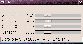
Accepts temperature data from the circuit and displays them on four horizontal sliders. Provides an option for resetting the microcontroller by lowering DTR, and has logic to detect lack of data flow. Currently does no logging (use the program above). Full source code is provided under the GPL license.
For programming your own PIC 12C509 microcontroller.
Drives the DS1820 sensors, obtains temperature readings, converts them to ASCII and sends them through the serial cable. Full source code provided, under the GPL license. Code was written to assemble using gpasm-0.0.6.
I'm happy for you to provide a link to this web page as your way of supplying the source code. Something like this:
| The source code for the software inside the microcontroller is <a href="http://quozl.netrek.org/ts/">available from the developer</a>. |
(Before the release, by purchasing the pre-programmed chip, you had purchased the right to use the software on the chip. You had not purchased any right to manufacture duplicates. The chips were programmed with the Code Protect bits set.)
Unlike most of my other work here, this project wasn't originally Open Source. It was too exotic for that.
I had wanted to see if I can make anything out of this type of work. I asked people to buy the chips. Nobody bought one off me directly, but I did end up selling a few hundred to Kitsrus. My return on investment was negligible. I don't consider it worth the effort to continue the project.
Measure the voltage on the supply pins for the microcontroller or the sensor. If it is below 4.75V, then the serial port is not supplying enough current. Options are either (a) change the serial port, (b) hook DTR and another signal line together to increase the current, (c) substitute another power source for DTR, such as from a 12V plug pack, of at least 20mA capacity, (d) use a low-dropout voltage regulator instead of the 78L05.
True. The code works well for DS1820 sensors. It works acceptably for DS18S20 sensors, with a slight degradation in reading accuracy. It doesn't work properly with the DS18B20.
The reason it doesn't work is that the data is in a different format inside the sensor. The bits are used for different purposes. I do have several DS18B20, but have not found the time to work on the problem. I'd also welcome code changes made by others, under the GPL.
This isn't provided here. Either buy a preprogrammed chip from others (which I no longer make any money on), or assemble the code yourself from source.
I don't provide the HEX file to people if they send me mail, either, because:
| Date | Change |
|---|---|
| 2006-07-29 | Add Darcs repository and Debian package links. |
| 2006-02-06 | Remove mailing list and add Wiki. |
| 2006-01-03 | Added link to Python implementation of tsl by Asgeir Nilsen. |
| 2003-06-10 | Corrected QKits location, thanks to Dennis Wallace. |
| 2003-06-04 | Added reasons why the hex file is not available. |
| 2003-03-11 | Tabulated the availability matrix. |
| 2003-01-18 | Patrick Brochu reveals that my schematic here has C and F swapped. |
| 2003-01-10 | Release tsl-1.2.tar.gz to fix off by one day error, reported by Stephen Kitchener in May 2002. |
| 2002-12-23 | Add FAQ. |
| 2002-06-26 | Dave Gomez spots an HTML error that suppresses most of the page for some web browsers. |
| 2002-05-10 | Add note about MPASM and TRIS instruction. |
| 2002-01-08 | Release patch for use with gpasm 0.9.13 or similar, which ignores the IF on line 1262 of ds1820.asm. |
| 2001-12-31 | Release source for program on microcontroller. |
| 2001-07-10 | Add test results for TSL.EXE on Microsoft Windows NT style operating systems, and remove request for results. Thanks to Chris Kirby and Lars Karlander. |
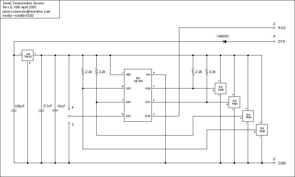
| 2001-04-10 | Fix schematic pull-up resistor connections |
| 2001-04-08 | Release version 1.1 of host data logging software |
| 2001-03-03 | Add emu fat freezer monitor link |
| 2001-01-13 | Release version 1.0 of host data logging software, fixing the logging of negative temperatures; the microcontroller was not affected |
| 2000-10-25 | Schematic fix, though it still has an error around the pull-up resistor connections |
| 2000-03-11 | Initial page and release of version 0.1 of host data logging software |
Date: Wed, 6 Oct 2004 11:16:39 +1000
To: peter crowcroft
From: James Cameron
Subject: Re: FW: Invoice from Quasar Electronics Limited

Customer wrote:
> 1. The module lacks any obvious method to allow it to be fitted in a
> box. I could use the jack posts on the D connector but the thickness
> of the box material would make the connection less reliable.

The PCB was by Peter.  I agree, there is no obvious method.

> 2. I note that the line separator used in the transmitted data is a
> linefeed (LF) character, rather than a carriage return (CR). DOS and
> Windows applications usually use the CR/LF character pair as an end of
> line marker. I believe that UNIX uses just a CR character.

This is incorrect.  The line separator used is a CR followed by LF, that
is, 0x0A followed by 0x0D.  See the function tx_crlf in the ds1820.asm
source file.  This is on line 512.  See the references to the function
elsewhere; after the welcome message and after each sensor reading.

If the customer is seeing only the LF character, there may have been a
framing error; where the baud rate of the transmitter does not match the
receiver.  The CR may have been dropped due to the error.

The most likely causes of a framing error are;

a) incorrect transmitter speed,
   a.1) incorrect operating voltage, caused by weak serial port,
   a.2) an overwritten OSCCAL value in PROM, caused by bad programming,
b) incorrect receiver speed,
   b.1) faulty receiver clock,
   b.2) incorrect receiver clock configuration,

Suggested procedure;

1.  optionally confirm that framing errors are occurring, using an
operating system or application that counts or reports the framing
errors,

2.  check that the voltage across the power supply pins of the PIC
12C509 is between 4.75 and 5.25V DC, and if it is outside that range
then correct it,

3.  check that the bit stream from the PIC 12C509 is being emitted at
2400 baud, plus or minus 5%,

4.  read back the PROM from the PIC 12C509 using a PIC programmer, and
examine the OSCCAL value for corruption,

5.  [Kitsrus, Quasar] check that the programming of the PIC 12C509 is
done from the original HEX file, and *not* from a HEX file read from
another 12C509, as this would corrupt the OSCCAL value,

If the OSCCAL value is corrupted, this can lead to the PIC RC oscillator
running at something other than the calibrated frequency.  The OSCCAL
value is set during factory calibration by Microchip, but can be
overwritten by programming.

--
James Cameron